
[BUILD LOG] Juice Box - Solar Power
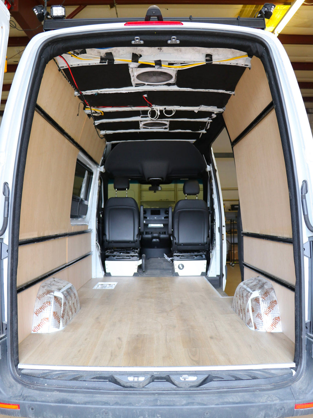
One of the major criteria for Juice Box (the 144” Mercedes Benz Sprinter) was to be able to travel off-grid for a period of time and still be able to run the electrical systems and charge personal devices. In order to accomplish this, we utilize solar panels to charge the house batteries. Collecting solar energy for an off-grid vehicle is a no-brainer (especially in the American Southwest). In this short article, I’ll discuss what the Juice Box system consists of, what products are used, and how they were installed.

In total, the system is fairly simple, and can be described by the components in their order from the panels to the batteries:
-
On the roof of the van there are (2) 100 Watt solar panels (for a total of 200 W) collecting solar energy.
-
They are connected in series with 10 AWG cables and MC4 connectors.
-
The two cables (1 positive and 1 negative) enter the van through a penetration plate, and are connected to a disconnect switch inside the electrical compartment.
-
This disconnect switch is connected to a solar charge controller which passes on the electrical power to the batteries via the bus bars, kill switch, and fuses (which will be covered in detail in future posts).
-
There are many things connected to those bus bars, so the solar panel input is just one part of the electrical system.
Components Used
SOLAR PANELS
(2) Renogy 100 Watt Monocrystalline Solar Panels
Size: Each panel is 42” x 21 x 1.5”
Install Method: These panels are designed to receive a mounting bracket that can be connected to a roof rack, roof rails, or directly to the van. In the case of Juice Box, a more simplified build, these brackets are screwed directly to the van. An automotive adhesive was applied to the van in the bracket mounting locations. Then the brackets were screwed to the van with the included self-drilling, gasketed hex head screws. Self-leveling sealant was applied over the brackets to prevent any water intrusion.
Wiring: The panels are equipped with a male and a female MC4 connector on a 12” 10AWG cable from the manufacturer. They are connected in series to each other (positive wire on one panel to the negative wire on the other panel), and to 10AWG cables that run into the van, and to the battery compartment.
PENETRATION PLATE
Size: 7” x 5” x 2”
Install Method: This cable entry plate (sometimes called a cable gland) has a feature that allows MC4 connectors to dock right at the entry plate, allowing the solar panels to be disconnected from the system from on top of the roof. This is super helpful for maintenance or for adding / changing solar panels. We opted to skip this feature and run the wires straight through. The plate is adhered to the van with automotive adhesive, screwed in with the included self-drilling screws, and sealed with self-leveling lap sealant.
Wiring: This can be outfitted with additional MC4 connectors, or you can run the wires straight through the glands like we did.
DISCONNECT SWITCH:
Size: 3” x 3” x 3”
Install Methods: The DIN rail is simply screwed to the inside of the battery compartment, and the breaker is clipped onto it. These are two of the most compatible pieces in the van. Literally built for each other.
Wiring: The 10AWG cables coming into the van through the cable entry plate are run into the battery compartment, and wired into the top of this disconnect switch. 10AWG cables are wired into the bottom of the switch and they run to the solar charge controller.
Note: The charge controller should be connected to the batteries (via the bus bars) before being connected to the solar panels. This is so that the controller can configure to a 12V system, and to avoid hitting the charge controller with unregulated current. It is also important to switch the disconnect to off, to disconnect the solar panels from the system before disconnecting the batteries. This will prevent arcing while working on the system.
SOLAR CHARGE CONTROLLER:
Size: 8” x 5” x 3”
Install Methods: The charge controller has a few mount points on the base, it can be screwed/bolted down in any orientation. It’s nice when you mount it somewhere where you can see the LED lights when working on it.
Wiring: The charge controller has two input terminals for the 10AWG wires (positive and negative) from the disconnect switch. There are two output terminals for the 10AWG wires that run to the bus bars (positive and negative). It also has it’s own separate ground connection. These are very clearly labeled on the charge controller.
Fuse: While the negative wire from the charge controller runs straight to the negative bus bar, the positive wire needs a fuse in between the charge controller and the bus bar. This protects the device, as well as the wiring between the bus bars and solar panels from overcurrent in the case of a short circuit or surge.
What’s It All For?
This solar panel system is charging (2) 100Ah LiFeP04 (Lithium Iron Phosphate) batteries. At nominal performance, it would take these panels 17 hours of optimal sun exposure, outputting 200W of power to charge the batteries from 0% to 100%. In practice, I have measured output levels of up to 160W in direct sun in Colorado in late fall.
Between the solar charging system, and the 200Ah of power storage, this system can easily power the 85L refrigerator, water pump, vent fan, and LED lights. It also serves to charge cell phones, laptops etc. It can also power the 2000W inverter that is used to output 110V power for running the induction cooktop and 110V outlets. With those devices, it is possible to quickly drain the system, and they are intended to be used sparingly. I will cover the remainder of the electrical system in future posts.